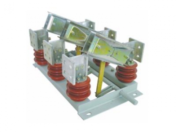
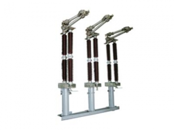
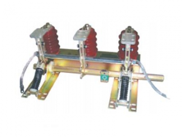
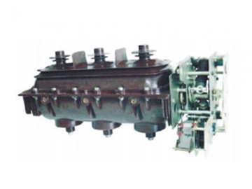
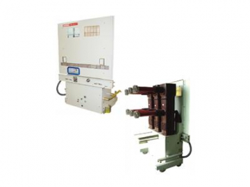
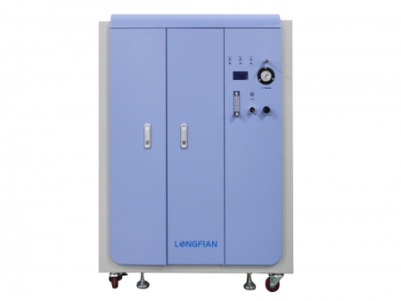
Disconnector (GN30-12 Indoor High Voltage Disconnect Switch)
Introduction
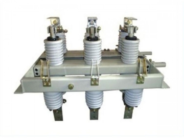
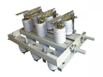
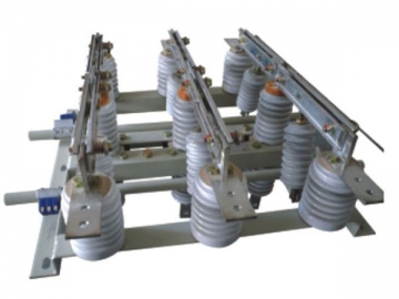
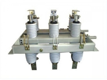
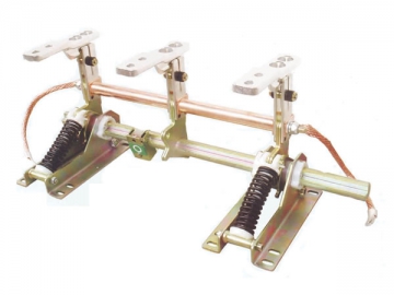
The GN30-12 indoor disconnector (hereinafter referred to as the disconnector) is a rotary switch of 12kV rated voltage, three-phase AC 50Hz for indoor use. This isolator switch is specially designed for XGN2-12, XGN66-12, HXGN-12 and other MV switchgears. The function of the disconnector is to make and break currents in the presence of no-load voltage, enabling the circuit breaker and the main bus to be isolated and grounded to ensure safe maintenance and reduce risks of accidents.
Service Conditions
1) Altitude: ≤1000m
2) Ambient air temperature: up to 40 ℃, down to -10 ℃, daily range of 15 ℃
3) Humidity: daily average relative humidity less than 95%; monthly average relative humidity less than 90%
4) Earthquake intensity: ≤ 8 degrees
5) Environmental conditions: no fire, explosion, severe dust, chemical corrosion and severe vibration;contamination class II.
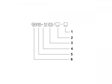
2. □ - rated operating current (A)
3. D – earthing device
4. 12 - rated voltage (kV)
5. 30 - design number
6. GN-indoor MV disconnector Technical Parameters of Indoor High Voltage Disconnect Switch
1. Mechanical Performance Parameters
| Item | Name | Unit | Parameters |
| 1 | Fracture opening distance | mm | 125 |
| 2 | Insulation distance | mm | 125 |
| 3 | Blade contact surface range | -- | 2/3 |
| 4 | Pole-center distance | mm | 210/230/250/275 |
| 5 | Three-phase closing simultaneity | ms | 3 |
| Item | Specification | Rated Voltage(kV) | Rated Current(A) | Reted Peak Withstand Current(kA) | 4S Thermal Short-time Withstand Current(kA) |
| 1 | GN30-12(D)/400-12.5 | 12 | 400 | 31.5 | 12.5 |
| 2 | GN30-12(D)/630-20 | 630 | 50 | 20 | |
| 3 | GN30-12(D)/1000-25 | 1000 | 63 | 25 | |
| 4 | GN30-12(D)/1250-31.5 | 1250 | 80 | 31.5 |
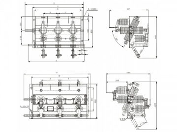
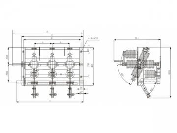
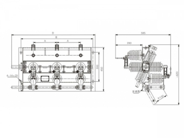
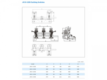
| Specification | A | B | C | D | E |
| GN30-12 | 210 | 680 | 720 | 800 | 810 |
| 230 | 720 | 760 | 840 | 850 | |
| 250 | 760 | 800 | 880 | 890 | |
| 275 | 810 | 800 | 960 | 970 |
Note:
1. Inlet and outlet: when terminal block is perpendicular to switch chassis mounting surface, it is vertical inlet and outlet; when terminal block is parallel to switch chassis mounting surface, it is horizontal inlet and outlet.
2. Definition of inlet and outlet end: for the upper and lower disconnectors, the end away from the circuit breaker is the outlet end, on the contrary, the one close to the circuit breaker, namely the one directly connected to the circuit breaker, is the inlet end.
3. Operating direction: facing the switchgear, the operating direction is left if the operating mechanism is positioned on the left, and vise versa.
We are a professional disconnector manufacturer and power distribution solution provider based in China. To find the best power distribution solutions, just find us!

