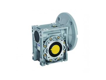
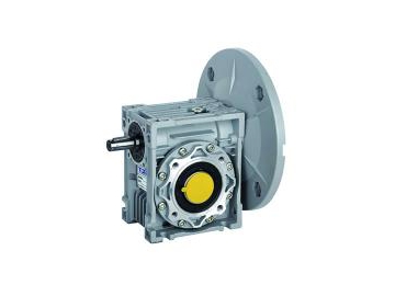
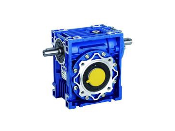
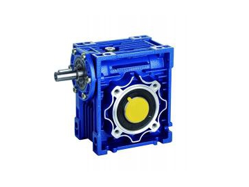
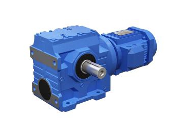
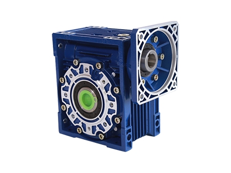
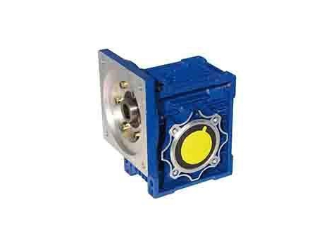
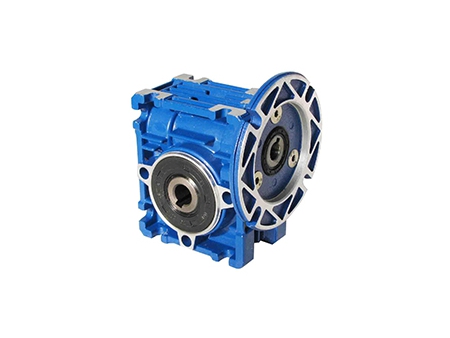
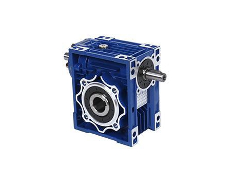
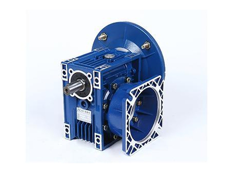
Aluminum Worm Speed Reducer
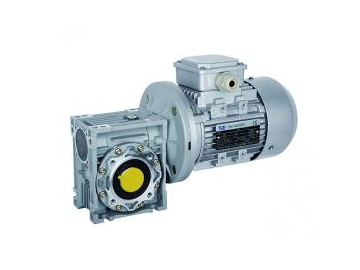
The NMRV gearbox is extremely practical, and seamlessly blends advanced technology from both at home and abroad for the highest possible efficiency and reliability. This gearbox can be paired with common motors, stepless speed variators, and flanged, electromagnetic clutch brakes with no need for couplers. This makes the worm gear speed reducer suitable for any direction mounting, and ensures the speed reducer offers a high output torque and stable operation.
· Industrial production lines
· Conveyance machinery
· Food machinery
· Medical equipment
· Printing machinery
· Office facilities
· Instruments
· Mechanical gaming tables
1. The worm gearbox is made of a high quality aluminum alloy, and is light weight, as well as rust resistant.
2. High output torque
3. The stable transmission and low noise ensures the worm gearbox is suitable for continuous work for long periods of time, even under harsh conditions
4. High heat radiation heat radiation
5. Streamlined design, durable, small volume
6. Suitable for omnibearing installation
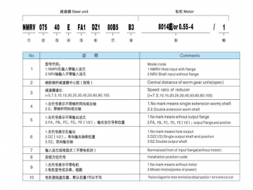
1. Types: The worm gearbox has input types that include a hole, shaft and extended worm shaft. It also has output types that include a hole, single shaft and double shaft.
2. Central distance of worm gear units: NMRV 030, NMRV 040, NMRV 050, NMRV 063, NMRV 075, NMRV 90, NMRV 110, NMRV 130, NMRV 150
3. Ratio: select the ratio closets to your needs to get the closest output speed
4. Input flange specification (when the gearbox doesn't have a motor)
5. Gearbox mounting position and terminal box position requirements
Main Material
1. Housing: Aluminum alloy (frame size from 025-090), cast iron (frame size from 110-150)
2. Worm: 20Cr. Using a carburizing and quenching treatment, the hardness of the gear surface is 56-62HRC. The thickness of the carburized layer is 0.3-0.5m after a grinding process.
3. Worm Gear: Wearable tin-bronze
Aluminum Alloy Housing
1. A pellet blasting treatment is carried out first, followed by a special antiseptic treatment to keep the silver and metal texture. This also adds to the corrosion resistance of organic solvents such as xylene.
2. An RAL5010 blue or silver coating is sprayed on after the phosphating process.
3. Cast Iron Housing: A red, rust prevention coating is first painted on, followed by an RAL5010 blue coating sprayed on.
Installation Caution for the Reducer
1. Check to ensure the rotational direction of the output shaft is correct before assembling the reducer with mechanical equipment.
2. Before the reducer is assembled with the original motor and equipment, the size deviation of each shaft diameter, bore diameter, key and key slot should be inspected to avoid affecting the performance of the reducer due to tight or loose assembly.
3. The reducer must be tightly mounted on the mechanical equipment to prevent looseness and vibration.
4. Avoid exposing the reducer to sun and other bad conditions.
5. If the reducer has been stored, unused, for 4 to 6 months, check to ensure the oil seal is still soaked in the lubrication oil. The oil seal lip may even stick to the shaft after losing its elasticity. As proper elasticity is essential to the oil seal's performance, users may need to change the seal.
6. All the rubber parts and air vent must not be stained with paint.
7. The mating component of the shaft should be coated in the lubrication oil in order to avoid getting stuck or oxidation when pairing with a reducer hollow shaft.
8. Please inspect the oil levels when using the reducer.
9. Do not start the reducer with a full load when using a new reducer, rather, gradually increase the load.
10. When the reducer is directly connected to the motor, a supporting unit should be set up for use if the motor weight is higher than the reducer.
11. Ensure the motor fan is in excellent ventilated conditions in case the radiation efficiency is influenced.
12. The standard working temperature of reducer ranges from -5 to 40°C. Please contact our technical staff is your working temperature needs are beyond that range.

