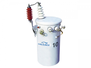
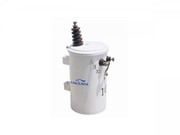
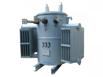
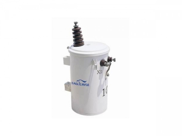
Completely Self Protected Single-phase Pole-mounted Distribution Transformer
Features
1. The completely self protected single-phase pole-mounted distribution transformer has high voltage porcelain bushing on the cover, and the bushing is equipped with eyebolt terminal that fits for copper or aluminum cable.
2. The low voltage bushings are fixed on the tank wall, and the annular shaped terminals are coated with tin on the surface.
3. Self-sealing pressure relief valve is applied.
4. The upper and lower hanger brackets are made from hot rolled steel, and they are welded to the tank. Additionally, they are fabricated in accordance with ANSI standard.
5. The one-piece fasten ring has several functions, such as extending the service life of our product, facilitating inspection process, maintaining uniform pressure around the entire rim, etc. It works together with a specially made tank rim, drawn cover and gasket to realize reliable sealing performance.
6. The ground connector is ring-type and bolted.
7. As the name implies, this product is able to protect itself against lightning, overload and short circuit, and the self protection system could also protect transmission and distribution lines from power failure when the transformer breaks down.
8. Compared with conventional type, the completely self-protected distribution transformer has similar parts including cylindrical tank, lifting lug, grounding device, core and winding, etc. However, it has some unique components as illustrated below.
a. One or two high voltage bushings are set on the cover, and a fuse is internally mounted in the bushing.
b. One or two lighting arresters, whose top ends are close to high voltage bushings, are installed on the tank wall, and they are connected to the high voltage bushings with the help of copper strips. On the other hand, the low voltage circuit breaker is placed inside the tank, and there are some other parts installed on the tank wall, such as operating handle, reset button, indicator light, etc.
c. Three low voltage bushings are on the tank wall, and the middle one, namely X2, is connected to the ground. For product with single high-voltage bushing, one end of the high-voltage winding is connected to the power grid, and the other end is connected to the group via tank wall.
Advantages
The completely self-protected distribution transformer could reduce the length of low voltage distribution lines and improve power supply quality. The wound core is proven to be an energy efficient design, and the pole-mounted method saves both space and money. With the help of this product, the low voltage power supply radius is cut down, and the line loss is 60% lower at least.
Aside from the above, this device shows good overload capability and allows simple maintenance, and it could deliver reliable performance is a continuous way.
Applications
Our completely self-protected distribution transformer is used to offer electricity to facilitate lighting system, agricultural production and industrial factory in rural places, remote areas and scattered villages, and it is also applicable for pole-mounted distribution lines for railways and urban power grids.
Technical Parameters
| Model | Rated power (kVA) | HV ratings (V) | Tapping range(%) | LV ratings (V) | Loss (W) | Dimensions (mm) | Weight (kg) | ||||||
| No-load loss | Full-load loss | A | B | C | D | E | Oil | Total | |||||
| 5 | 33000/19000, 30000/17321, 20000/11547, 13200/7620, 11000/6350 or others | ±2×2.5% or others | 120-240, 240-480, 250-500 or others | 29 | 95 | 860 | 430 | 510 | 340 | 286 | 15 | 92 | |
| 10 | 46 | 121 | 910 | 470 | 550 | 380 | 22 | 150 | |||||
| 15 | 58 | 215 | 970 | 500 | 580 | 410 | 30 | 210 | |||||
| 25 | 82 | 295 | 1025 | 550 | 630 | 450 | 45 | 258 | |||||
| 37.5 | 110 | 400 | 1225 | 630 | 680 | 520 | 50 | 340 | |||||
| 50 | 140 | 490 | 1235 | 630 | 680 | 520 | 62 | 395 | |||||
| 75 | 275 | 670 | 1300 | 680 | 720 | 550 | 591 | 88 | 480 | ||||
| 100 | 300 | 881 | 1350 | 780 | 810 | 610 | 94 | 530 | |||||
| 167 | 350 | 1400 | 1460 | 830 | 890 | 660 | 138 | 680 | |||||
| 250 | 650 | 2530 | 1570 | 960 | 950 | 660 | 250 | 990 | |||||
| 333 | 700 | 3500 | 1660 | 960 | 960 | 660 | 300 | 1160 | |||||
Note: The above data are typical values andare for reference only. Customized products are supplied upon request.
Table 2: DH15 Series with AmorphousMetal Core for Foreign Area| Model | Rated power (kVA) | HV ratings (V) | Tapping range (%) | LV ratings (V) | Loss (W) | Dimensions (mm) | Weight (kg) | ||||||
| No-load loss | Full-load loss | A | B | C | D | E | Oil | Total | |||||
| 5 | 33000/19000, 30000/17321, 20000/11547, 13200/7620, 11000/6350 or others | ±2×2.5% or others | 120-240, 240-480, 250-500 or others | 7 | 103 | 840 | 400 | 480 | 310 | 286 | 17 | 75 | |
| 10 | 10 | 180 | 864 | 430 | 510 | 340 | 24 | 100 | |||||
| 15 | 14 | 210 | 914 | 430 | 510 | 340 | 26 | 125 | |||||
| 25 | 18.5 | 320 | 1041 | 480 | 560 | 380 | 33 | 162 | |||||
| 37.5 | 24 | 500 | 1120 | 520 | 610 | 450 | 54 | 240 | |||||
| 50 | 95 | 375 | 1245 | 520 | 610 | 450 | 62 | 295 | |||||
| 75 | 135 | 580 | 1245 | 600 | 680 | 510 | 591 | 78 | 420 | ||||
| 100 | 154 | 960 | 1270 | 640 | 710 | 510 | 89 | 465 | |||||
| 167 | 176 | 1460 | 1470 | 940 | 840 | 610 | 140 | 650 | |||||
| 250 | 220 | 1900 | 1560 | 1260 | 960 | 660 | 250 | 950 | |||||
| 333 | 260 | 2600 | 1660 | 1260 | 960 | 660 | 300 | 1200 | |||||
Note: The above data are typical valuesand are for reference only. Customized products are supplied upon request.
Table 3: D11 Series with CRGO Core forDomestic Area| Model | Rated power (kVA) | HV ratings (V) | Tapping range (%) | LV ratings (V) | Loss (W) | Dimensions (mm) | Weight (kg) | ||||||
| No-load loss | Full-load loss | A | B | C | D | E | Oil | Total | |||||
| 5 | 10000 | 0 or ±2×2.5% or ±5% | 220-230 or 440-460 | 35 | 145 | 790 | 440 | 530 | 330 | 286 | 22 | 80 | |
| 10 | 55 | 260 | 820 | 440 | 530 | 330 | 25 | 100 | |||||
| 16 | 65 | 365 | 870 | 440 | 530 | 330 | 30 | 125 | |||||
| 20 | 80 | 430 | 870 | 470 | 560 | 360 | 35 | 140 | |||||
| 30 | 100 | 625 | 1060 | 610 | 610 | 410 | 65 | 205 | |||||
| 40 | 125 | 775 | 1060 | 660 | 660 | 460 | 70 | 250 | |||||
| 50 | 150 | 950 | 1080 | 760 | 660 | 460 | 591 | 80 | 280 | ||||
| 63 | 180 | 1125 | 1110 | 860 | 660 | 460 | 80 | 320 | |||||
| 80 | 200 | 1400 | 1180 | 895 | 690 | 496 | 95 | 380 | |||||
| 100 | 240 | 1650 | 1230 | 935 | 690 | 496 | 105 | 435 | |||||
| 125 | 285 | 1950 | 1280 | 960 | 720 | 524 | 120 | 510 | |||||
| 160 | 365 | 2365 | 1340 | 1160 | 760 | 560 | 150 | 615 | |||||
Note: The above data are typical valuesand are for reference only. Customized products are supplied upon request.
Table 4: DH15 Series with Amorphous MetalCore for Domestic Area| Model | Rated power (kVA) | HV ratings (V) | Tapping range (%) | LV ratings (V) | Loss (W) | Dimensions (mm) | Weight (kg) | ||||||
| No-load loss | Full-load loss | A | B | C | D | E | Oil | Total | |||||
| 5 | 10000 | 0 or ±2×2.5% or ±5% | 220-230 or 440-460 | 15 | 145 | 790 | 440 | 530 | 330 | 286 | 20 | 80 | |
| 10 | 18 | 260 | 820 | 440 | 530 | 330 | 22 | 100 | |||||
| 16 | 22 | 365 | 870 | 470 | 560 | 360 | 30 | 130 | |||||
| 20 | 25 | 430 | 870 | 470 | 560 | 360 | 35 | 145 | |||||
| 30 | 30 | 625 | 1060 | 610 | 610 | 410 | 60 | 220 | |||||
| 40 | 35 | 775 | 1060 | 660 | 660 | 460 | 70 | 250 | |||||
| 50 | 40 | 950 | 1080 | 796 | 696 | 496 | 80 | 280 | |||||
| 63 | 50 | 1135 | 1110 | 896 | 696 | 496 | 591 | 90 | 370 | ||||
| 80 | 60 | 1400 | 1180 | 924 | 724 | 524 | 100 | 415 | |||||
| 100 | 70 | 1650 | 1230 | 1000 | 760 | 560 | 110 | 485 | |||||
| 125 | 85 | 1950 | 1280 | 1050 | 810 | 610 | 120 | 510 | |||||
| 160 | 100 | 2365 | 1340 | 1260 | 860 | 660 | 210 | 765 | |||||
Note: The above data are typical valuesand are for reference only. Customized products are supplied upon request.
Related Names
Encapsulated Power Transformer | 100 KVA Transformer | Alternating Current Transformer
