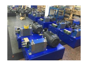
Hydraulic Drive System
Hydraulic Drive Systems with Power Engine
The hydraulic system is used to increase the acting force by changing pressure. A complete hydraulic system consists of five parts, the power element, the actuation element, the control element, the auxiliary element (accessory) and the hydraulic fluid. Hydraulic systems can be divided into two categories: hydraulic drive systems and hydraulic control systems. The hydraulic drive system is primarily designed to transmit power and motion. The hydraulic control system is such that the hydraulic system output meets specific performance requirements (especially dynamic performance). The so-called hydraulic system is mainly referred to as the hydraulic drive system.
CATSU's hydraulic systems are widely used in:
Water conservancy project: dam, hydraulic system of hydropower station, hydraulic system of turbine governor, hydraulic system of gate hoist, hydraulic system of ship lift.
Machine tool industry, such as grinding machines, milling machines, planers, broaching machines, presses, shearing machines and modular machine tools.
Metallurgical industry, such as electric furnace control systems, rolling mill control systems, open hearth charging, converter control systems, blast furnace control systems, constant tension devices, etc.
Construction machinery, such as excavators, tire loaders, truck cranes, crawler dozers, tire cranes, self-propelled scrapers, graders and vibratory rollers.
Agricultural machinery, such as combine harvesters, tractors, etc.
Textile industry, such as plastic injection molding machines, rubber vulcanizers, paper machines, printing machines and textile machines.
Shipbuilding industry, such as full hydraulic dredgers, piling vessels, oil production platforms, hovercrafts and marine auxiliary machinery.
Other: sun tracking system, wave simulation device, ship driving simulator, rocket-assisted launching device, aerospace environment simulation and high-rise building anti-shock system and emergency braking device, etc.
Hydraulic systems and partsHydraulic system principle diagram
| No. | Parts | Code | Quantity | Brand |
| 1 | Oil tank | YX-200 | 1 | CATSU |
| 2 | Motor | 7.5KW-4-B35 | 1 | SIEMENS |
| 3 | Oil pump | CBQT-F532/F416-AFPR | 1 | HEFEI CHANGYUAN |
| 4 | Fluid level gauge | YWZ-200 | 1 | |
| 5 | Air filter | QUQ2 | 1 | LEEMIN |
| 6 | Check valve | CV10W-20-17N | 1 | WINNER |
| 7 | Check valve | CV12W-20-17N | 1 | WINNER |
| 8 | Overflow valve | RP10W-20AL | 1 | WINNER |
| 9 | counterbalance valve | CBCA-LHN | 1 | SUN |
| 10 | Magnetic exchange valve | 4WE10H62N/G24 | 1 | |
| 11 | Pressure gage and switch | AT63-250/AQM6T | CATSU | |
| 12 | Pressure sensor | PT3551 | 1 | IFM |
| 13 | Oil filter | MF-12 | 1 | LIANGJING |
| 14 | Pilot operated check valve | CKCB-XCN | 1 | SUN |
| 15 | Overflow valve | RP10W-20AL | 1 | WINNER |
| 16 | Magnetic check valve | EP10W-2A-01N/DC24 | 1 | WINNER |
| 17 | Throttle valve | NV-08W-20 | 1 | WINNER |
| 18 | Pressure page | AT63-70 | 1 | CATSU |
Hydraulic components
Hydraulic motor, hydraulic pump, manifold block, hydraulic valve, hydraulic pipe, hydraulic joint, the components of our agent brands are as follows:
